and scans of magazine articles or adverts about some of its components
with grateful thanks to the excellent worldradiohistory.com
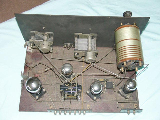
Drawing of the physical layout of my wireless
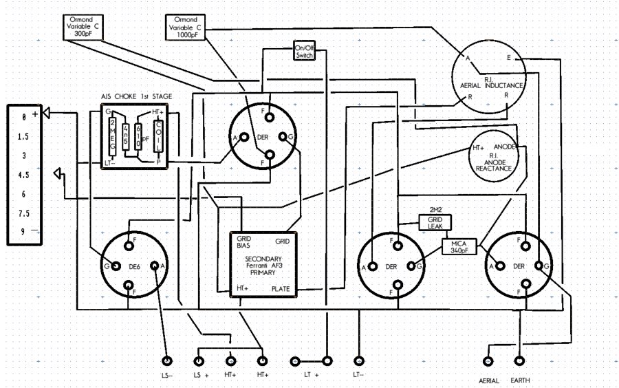
Circuit diagram of the above. This will need to be revised (rheostats for heaters)
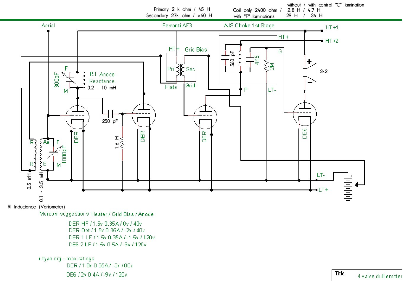
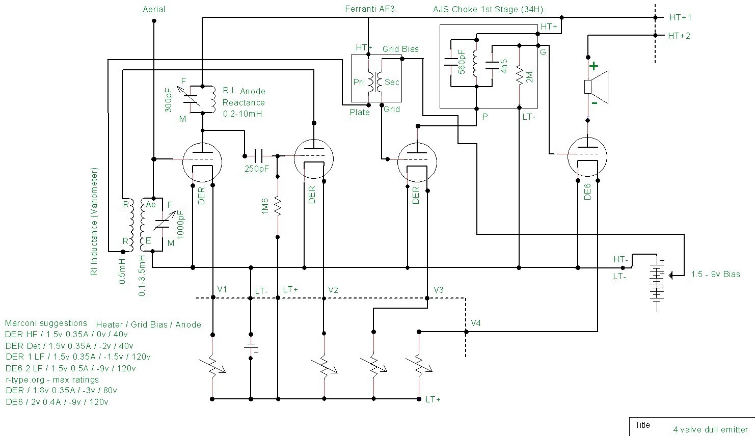
Circuit diagram revised - HT2 to speaker/V4, HT1 to AJS choke, rheostats for heaters)
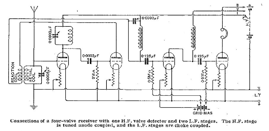
A circuit I found where my wireless matches the first stages (V1, V2) of this design
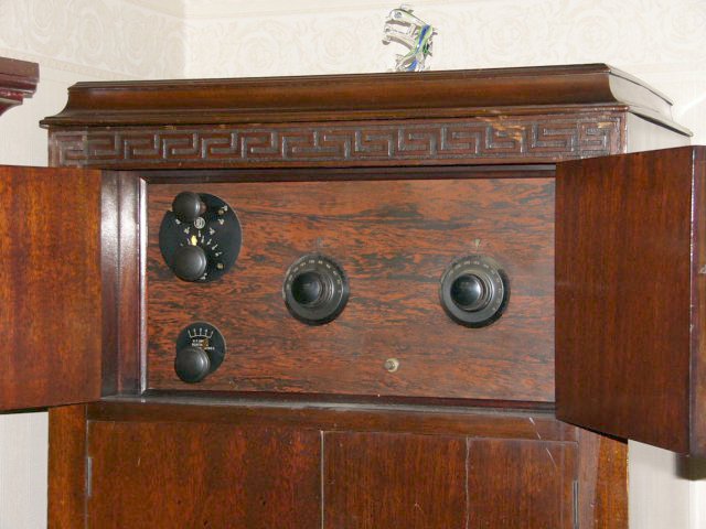
The set is built into a cabinet which I think originally housed a gramophone
Front panel
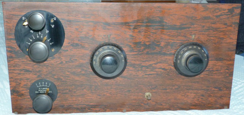
Top left, between the 300pF variable and DE6 is a space for the (under restoration) AJS choke
Adverts for the "variometer"
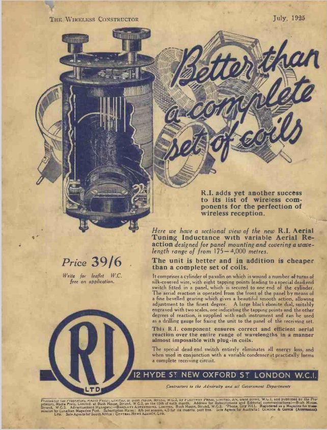
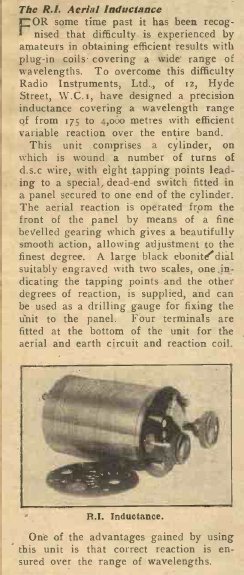
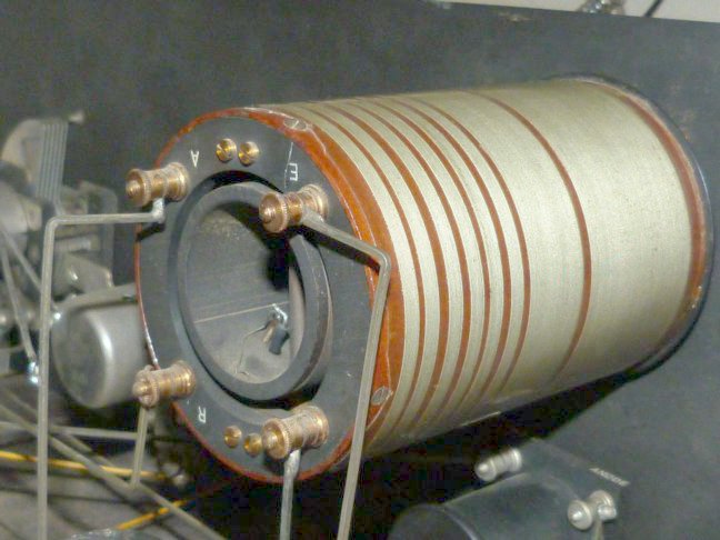
The beautifully engineered RI variometer / tuning inductor
Note the square cross-section, wiring used throughout the set
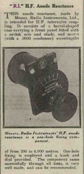
Advert for the anode reactance unit
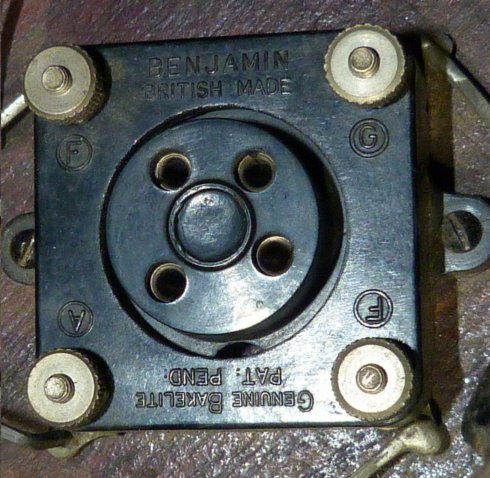
Benjamin valve holder
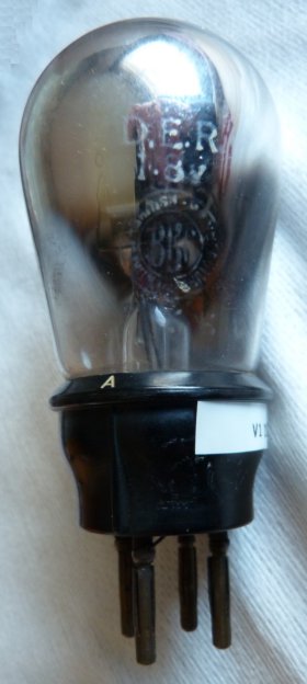
DER valve (V1, V2, V3)
DE6 valve (V4)
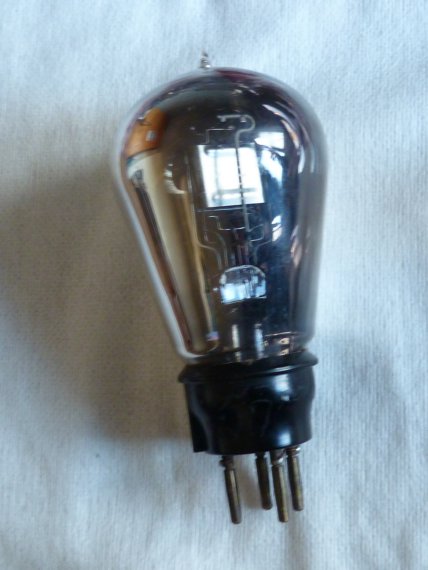
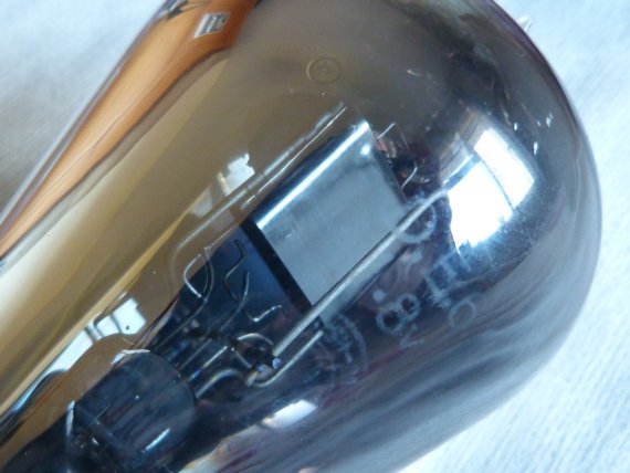
Another photo of the DE6 where the markings D.E.6 and 1.8v are visible
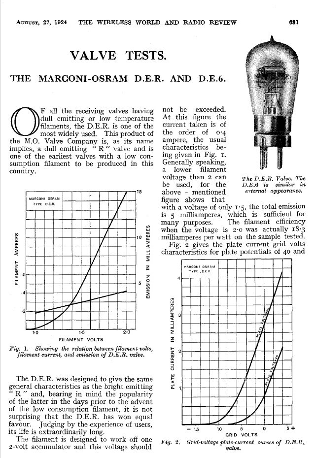
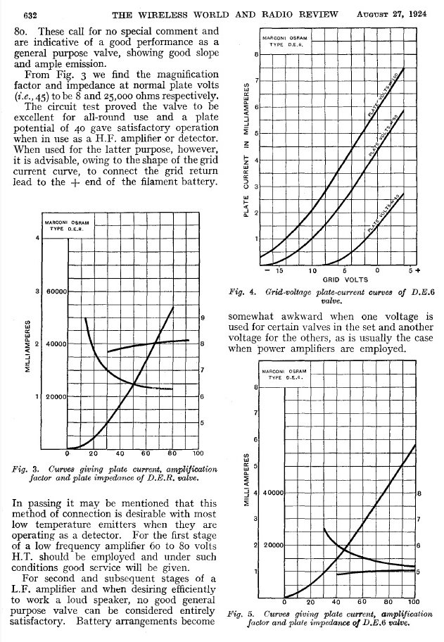
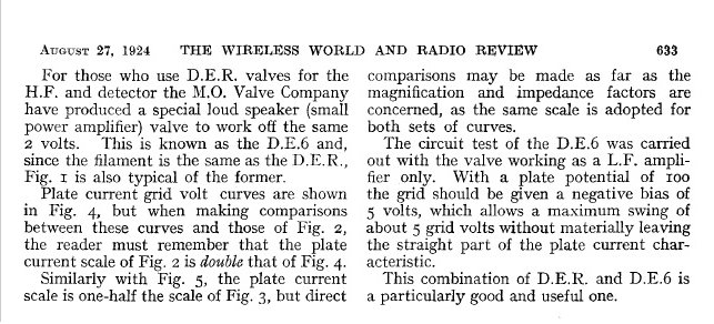
Marconi-Osram DER and DE6 valve data
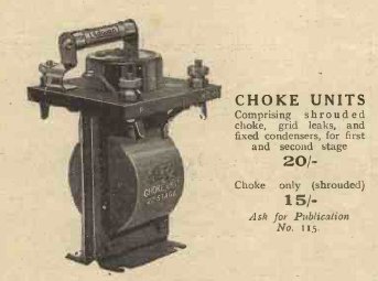
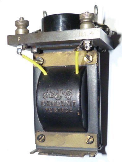
Advert for the AJS choke, grid leak resistor, condensers
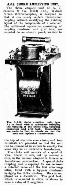
Another advert for the AJS choke with more detail
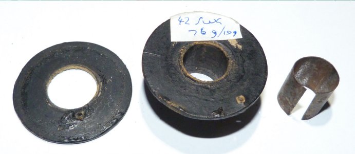
The choke was open circuit. I removed all the 42swg wire to reveal the cardboard(?) former
but weighed it before and after so I could work out (approximately) the length of wire
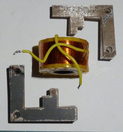
Replacement coil (approx 11,500 turns of 42 swg ECW) wound onto a Delrin former
Kapton tape was placed on the turns at intervals and on the completed coil
The iron laminations were cleaned up and, as shown, will be inserted into the coil
Re-assembled choke (but may have to be dismantled if the inductance is too high)
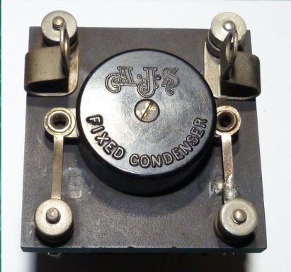
Showing the cleaned-up condenser. Grid leak resistor to be fitted into the clips
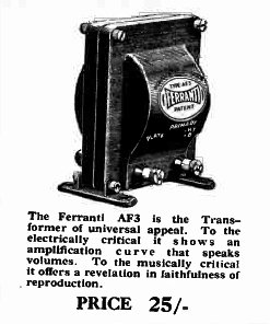
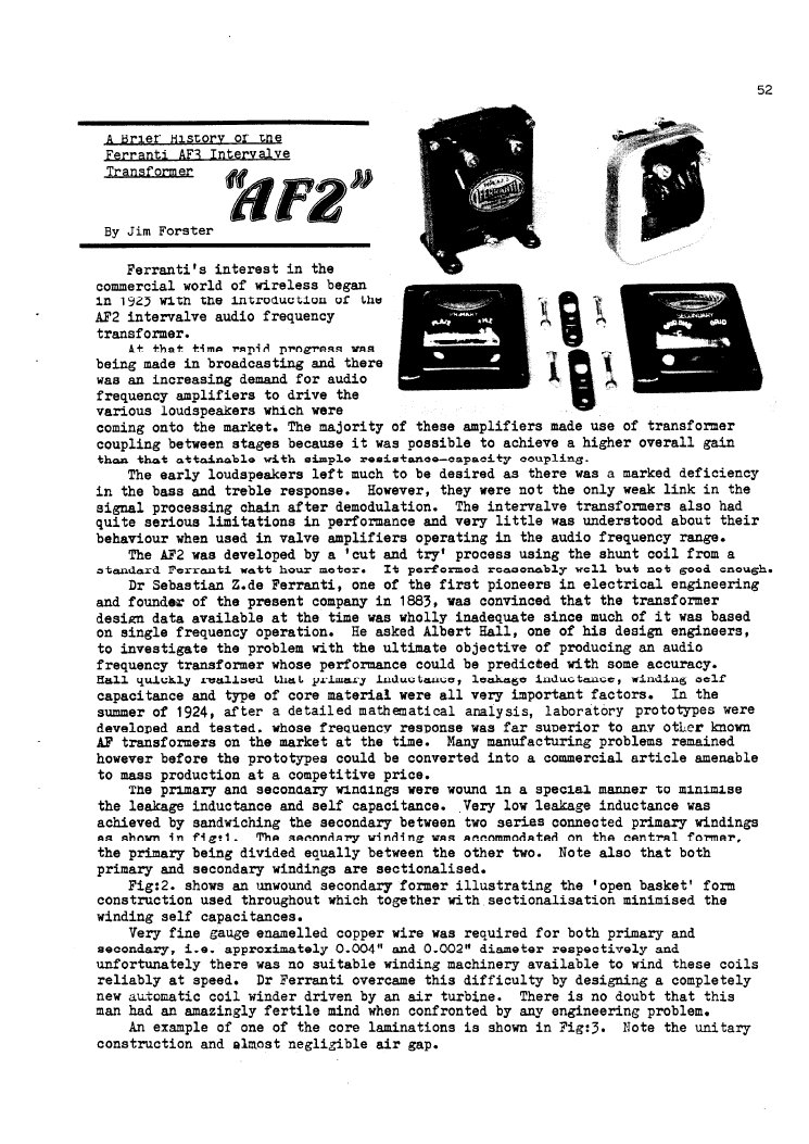
Advert for the Ferranti AF3 transformer
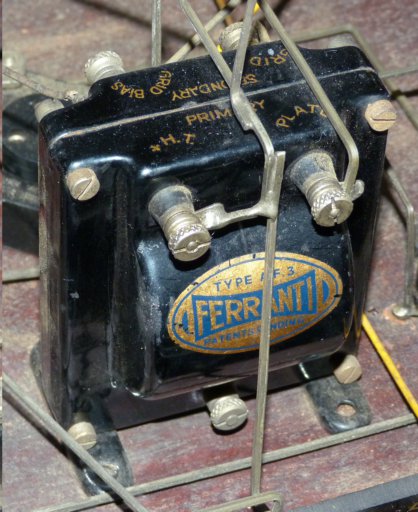
My transformer. Again note the square cross-section, uninsulated wire
From articles I have read this was very common in the 1920s
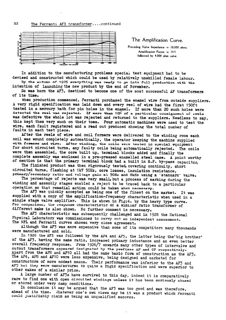
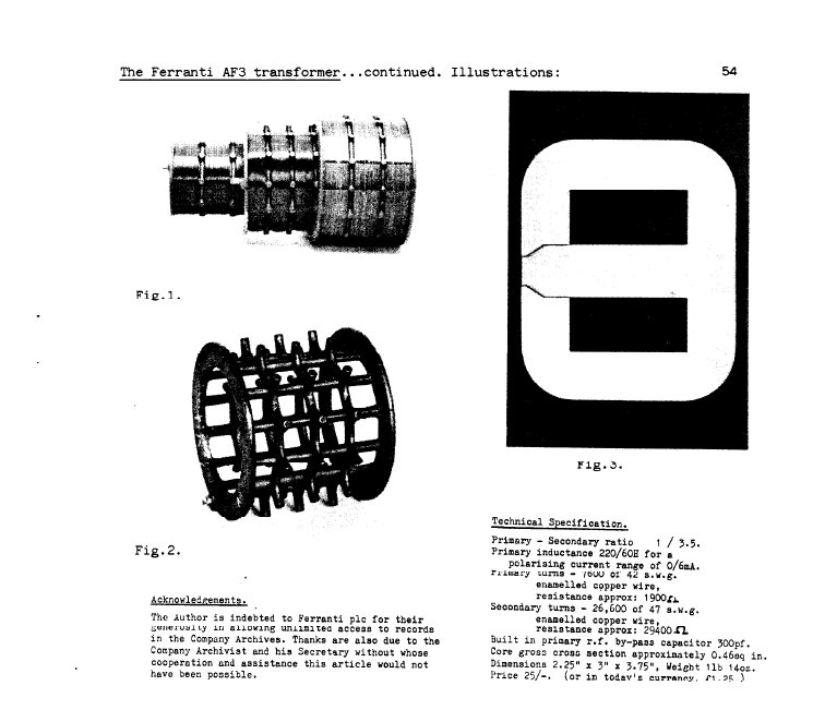
An article from the BVWS (British Vintage Wireless Society) Bulletin. Volume 9, Number 3
with detail about the design, construction and specifications of the Ferranti AF3
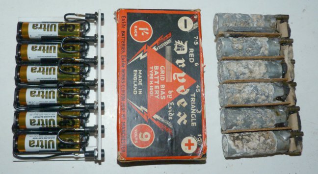
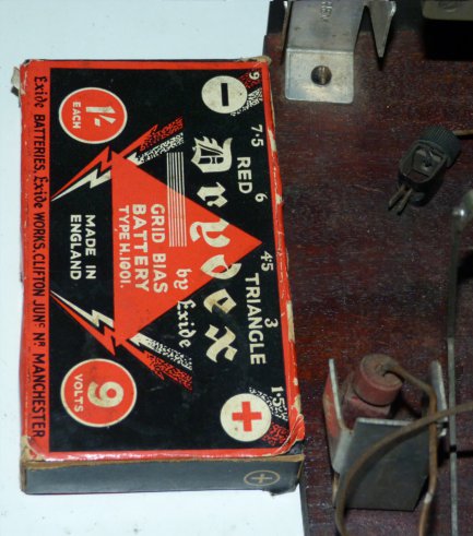
Grid bias battery. I managed to removed the original cells from the cardboard sleeve
Left is the replacement battery I made
Brackets to hold the grid bias battery
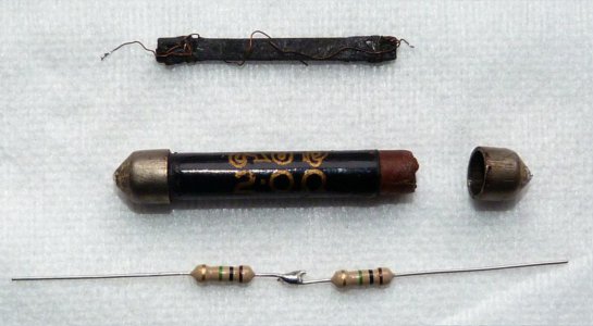
2Mohm grid leak resistor. Original measures approximately 5Mohm
2 x 1Mohm 0.5W carbon film fitted into the original tube.
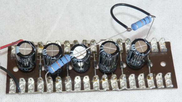
A lash-up of a voltage multiplier. To be fed with 15v AC, 5 x 1N4007, 5 x 100uF 100V
The 10k 2W resistors were fitted to simulate current drawn by the anodes once the wireless is powered up
2 x 10k in series (= 20k) gave 18.5v, 36.6v, 53.9v, 71.2v, 87.5v at 4.375 mA
1 x 10k gave 17.9v, 34.6v, 49.5v, 64.5v, 78.4v at 7.84 mA
I plan to use the 5th voltage for the DE6, 4th voltage for the DER valves
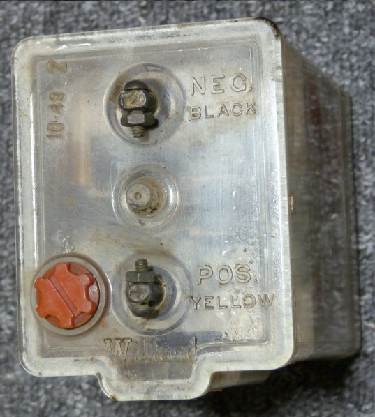
The original 2 volt battery for heaters. Not recoverable! I plan to replace it with a 2v 5Ah Cyclon cell
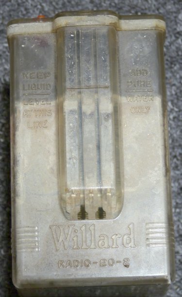
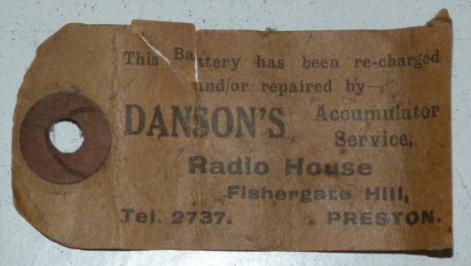
A label with the 2v battery showing it had been recharged(?) by Danson's, Radio House, Fishergate Hill, Preston
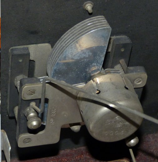
Ormond 300pF variable "condenser"
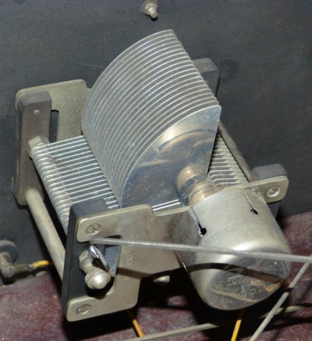
Ormond 1000pF variable "condenser"
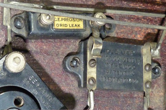
CE Precision grid leak resistor (approx 2.2Mohm) and Dubilier Mica Condenser (approx 340pF)
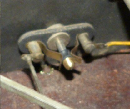
A basic pull-for-on switch. I plan to bypass this - the contacts are poor and may not restore well.
Also I need to re-wire the LT+ wiring to incorporate rheostats for each valve to control heater voltages.
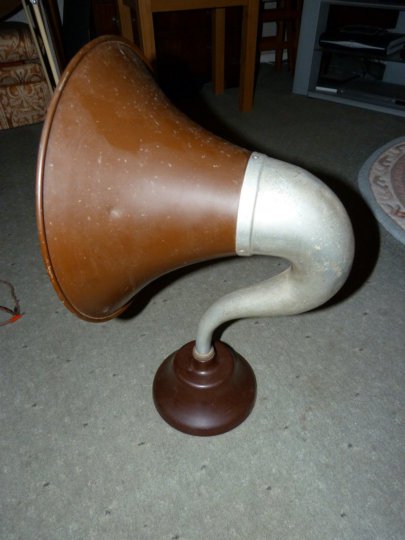
My BTH horn loudspeaker. 14 inch diameter
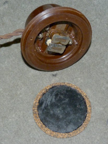
The 2.2k ohm driver of the BTH speaker. This appears to have permanent magnets and the wires are colour coded
red and black. Red goes to HT+. Connecting the wrong way round risks de-magnetising the magnets
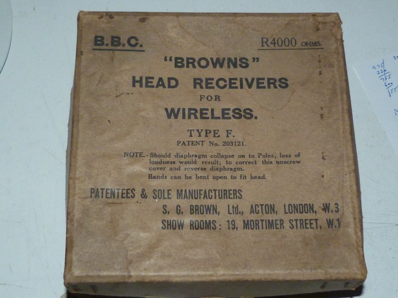
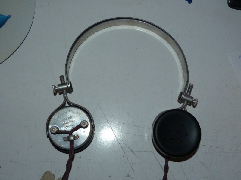
I also have a "Browns" head receivers for wireless, Type F, 4000 ohms
but I think these are more suited to a wireless receiver with a lower volume output